Home | FAQ | CAE News | Contact Us

The Custom Shop
D.I.Y. Pedalboard Assembly Guide
INTRODUCTION
As you may know, I am probably best known for my more elaborate (and complicated) guitar system designs. However, I have certainly designed and built my fair share of more “traditional” pedalboards for over 29 years in this business of crafting high quality professional guitar rigs. The following information is meant as merely a guideline.This is in no way the only way to build your own pedalboard, as there are many options, and many resources available on the internet from which to guide you.
I consider this a simple “surface-mount” type of board, where everything is mounted on the top side of a flat surface.This is typical of many pedalboards in use today.Of course,there are many alternatives to this type of configuration. This is just my approach to this particular group of pedals that I wanted on this type of board. I will explain in detail the reasons for my choices, in the hope you will gain some insight in the planning and building of your own board.
PLANNING–WHATS IT GONNA DO?
Take the time to plan it out carefully.What is the intention? What sounds do you need to achieve? Do you need to duplicate the sounds on a record? Or is it just for some sonic experimentation? Building a professional pedalboard requires organization and some thought, otherwise, you could just string all your pedals together on the floor and have at it. That doesn’t make it much fun for soundchecks at the start, or tear-down at the end of the night. Not to mention reliability/troubleshooting. I wanted my board to represent some of the basic sonic “food groups” a modern guitar player would require ie: Overdrive, wah pedal, modulation stuff, delay, and perhaps some weird stuff for fun.
PLANNING–SIZE MATTERS
What your pedalboard has to achieve sonically will also ultimately determine the size as well. And keep in mind if you are a touring professional, this thing has got to come in at 70lbs or under(in its road case!) if you want to get it on a plane as excess baggage.
I decided to work within some limitations. Mainly, pedals I had on hand, and a physical size of 17″ x 28″. This is because I used 2 leftover CAE 3+ Tube Preamp chassis top covers joined together as a top mounting surface of my board. These are black powder coated steel, and make a fine smooth (and pretty) surface on which to attach everything. If I was building this for a client, I would have A&S Case Company make me a “mounting board” out of black filon laminated wood, trimmed with aluminum channel to the exact size necessary to hold all the pedals.I developed this approach with A&S over 25 years ago, and these boards are ubiquitous today.
So I went to Home Depot, got a plank of 3/8″ plywood, and cut it to size. I added “t-nuts” on the top side in order to attach the rubber feet from the opposite (floor)side, since the “t-nuts” would be covered my the surface covers.
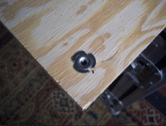 | 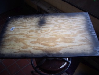 |
Also,I measured and added “t-nuts” on the floor side for mounting and securing the AC plug strip and power supply from the top side(more on this later).I painted the wood edges flat black for a nice look.
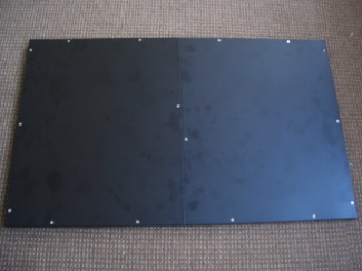 I then secured the steel chassis covers to the top surface of the wood “board” with flat head wood screws.
I now had a pedal board mounting surface. Time to arrange the pedals on the board.
But what pedals?
PICK YOUR POISON(S)
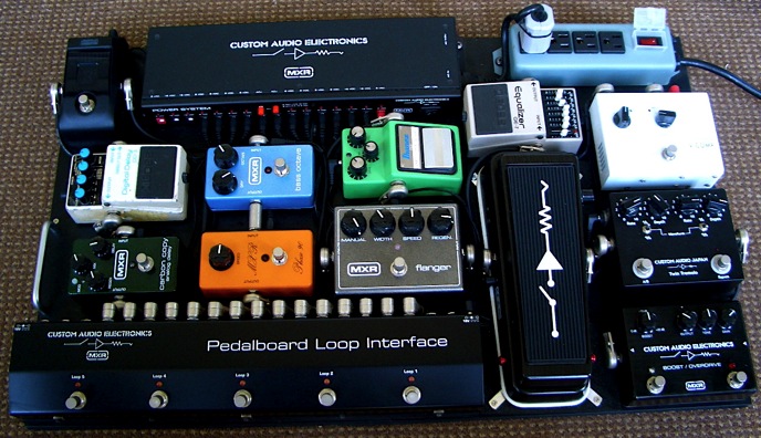
I knew I wanted to feature the CAE/MXR Boost/Overdrive, Dunlop/CAE Wah, and the CAE/MXR Power System, as well as the new Pedalboard Loop Interface (more on that later). I also wanted to include pedals from my friends and associates at Custom Audio Japan, the V-Comp, and the Twin Tremolo. I wanted another “modulation” option, so I went with an old favorite, the MXR Flanger. Of course, The Ibanez TS-9 is great for its midrange growl, and a perfect complement to the CAE/MXR Overdrive voicing.There was room for a couple more “manglers”, so I went with a MXR Blue Box, and Bass Octave pedal. I’ve got to have some delay, so I used a MXR Carbon Copy (dark but cool) and an old beat down Boss DD-3, still functional, but sounding great.I also used a Boss GE-7 Equalizer for some “tone shaping”.That left a tuner. I didn’t have much room left, so I used a little Korg Pitchblack, which worked out great.
Thats 12 things in my signal path(assuming everything on, of course), and 13 if you count the Loop Interface, which I do.
ORDER UP!–PHYSICAL PLACEMENT AND SIGNAL PATH
Ergonomics and signal path go hand in hand with me. And most important is sonic integrity.I don’t like cables flying back and forth across a pedalboard for no good reason.It’s messy and confusing.Physical placement of pedals is very important as well, since you have to be able to get to everything with your foot.
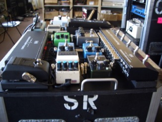
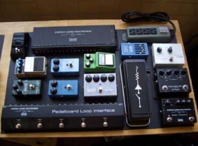 So physical placement tends to follow the signal path as much as possible on any board I build, with some exceptions, as we will see.I spent a long time (more than a day) laying the pedals out in different locations to best suit my needs.
Take your time here. Its worth it. After all, you will have to live (and work) with it once the project is completed. This is where the Pedalboard Loop Interface(PLI) becomes imperative. This gives you the best of both worlds: an ergonomically useful strip of foot-switchable loops for routing your signal to and from pedals (or groups of pedals in this case). That,along with a clean and quiet signal path with optional high-headroom signal buffer/line drivers. The PLI has 5 passive(relay)series routing loops configured as follows: 3 loops in a series chain with a common input/output, and 3 sets of sends/returns.This then feeds 2 discrete loops with individual inputs/sends/returns/outputs. At the beginning and end of this normalled chain of 5 loops are high quality signal buffer/line drivers with their own input/output jacks. This way you can choose to use the buffers (or not) patch in between the loops, or plug into Buffer #1 input and come out Buffer#2’s output with 5 loops in between.You can also use the discrete loops 4 or 5 as output A/B’s for selecting amps, and/or use the 3 loop “chain” as a switchable signal splitter.
The pedalboard’s signal path (and reasons for it ) is as follows:
I wanted the input to the board at the lower right hand corner, so I used the CAE/MXR MC402 Boost/Overdrive at this position,first in the chain.I like some crunch before the wah, and this also gives the option of a clean boost at the beginning of the chain as well, if needed.
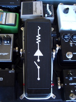
Next comes the Wah, with its switchable Fasel inductors, built in boost, and 100% bypass, this is a perfect spot in the chain. I opted to elevate this pedal somewhat, in order to safely pass cables underneath it. I used some Keystone angle brackets pounded flat as anchors to secure the wah to the wood “elevators”.This makes for a secure attachment for something you have to step on with some degree of force. And I didn’t have to modify the pedal at all.
The Wah then feeds the input of the 3 loop chain on the PLI, which takes up the bottom left/center of the board, with its switches where they need to be…near your feet. I opted to bypass the first buffer in the PLI, as I didn’t think it was necessary at this point in the signal path. My thoughts were confirmed when I tested the system. I set the boost to unity (no boost) on the MC402, and kicked it in and out to act as a buffer. No audible change. This meant I didn’t need the buffer in the PLI.
PLI LOOP ASSIGNMENTS
Loop 1 of the PLI gets the CAE (Japan) V-Comp, a lovely tube compressor. Very clean with a nice subtle compression. Great after the Wah/MC402, but before the TS-9. Elevated, even though its bypass footswitch is never used, to allow for space saving right angle connectors.
Loop 2 of the PLI gets the “manglers”, the Bass Octave and the Blue Box,in that order. They want to see a relatively clean signal, so I keep them early in the chain. They are physically low on the board as they are pretty much set and forget, except for the decision as to which on is “on”, since the PLI Loop 2 switch does the bypassing.
Loop 3 of the PLI has the TS-9 Tube Screamer.Its good to have a little crunch after wah/compression, and since it has an active bypass, putting it in a passive PLI loop keeps the signal path cleaner.Its physical position, although somewhat “hidden” is fine since the PLI loop 3 switch does the bypassing.
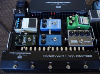
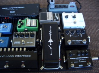
At this point, the signal leaves the PLI ( via the 3 loop chain output) and goes to the CAJ Twin Tremolo>MXR Flanger (in that order) and then back to the PLI Loop 4 input.This is where I want “modulation” in the signal path, and the PLI gives me the perfect patch points to put them there. This is also fine by me since both pedals are 100% hard wire bypass.
In addition, if there was ever any trouble at this point in the signal path, either with the pedals, or the cables connecting them, I could eliminate this portion of the path by simply pulling out the cable connected to Loop 4’s input. Since the inputs/outputs, (and sends/returns on the L1,L2,L3 “chain”) are half normalled on the PLI, the signal would continue uninterrupted. The MXR Flanger and CAJ Twin Tremolo are elevated with wood blocks glued to the metal surface of the board to allow access to their bypass switches.
 |  |
Loop 4 of the PLI gets the Delays. Boss DD-3 and MXR Carbon Copy in that order. The CC is hard wire bypass, but the DD-3 is not, so it is good to have in a passive PLI loop, again to keep the signal path clean and as passive as possible.
At this point, the signal again leaves the PLI (via the Loop 4 output jack) and goes to the Korg PitchBlack Tuner, then returns to the PLI Loop 5 input. This is where I break with convention somewhat. First, I want to be able to Mute/Tune, and the PitchBlack allows this with hard-wire bypass.Second, I needed foot access for this. And typically, I would put the tuner closer to the beginning of the signal path. But I am at least smart enough to know to shut off effects (especially modulation stuff)when tuning, so further down the path didn’t concern me too much.So the only other place it could have gone physically was above the Wah, but with somewhat restricted access, so I chose to put it where it is, upper left hand corner, elevated for foot access.If I didn’t need to mute, I could have just sent signal to it (via Loop 4 out).As it is, if there was any problem with the tuner itself, or the cables connecting it to the PLI, I could just pull the cable connected to Loop 5’s input, and the PLI’s internal normalling would allow the signal to continue uninterrupted.
This brings us to the last loop, Loop 5. This gets the Boss GE-7 EQ. I like clean boosts at the END of the signal path, just to pound the amp’s input a little harder, without affecting anything else in the chain. Plus I already have a clean boost in the front end, with the MC402. The EQ obviously allows for tonal shaping as well as a clean boost, if needed. I sometimes plug this board into one of those Epiphone Valve Junior amps (those 1 knob things) which are a little dark, so the EQ helps brighten them up a little.
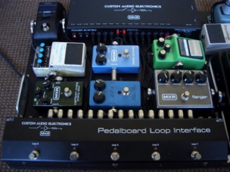 At this point, the signal leaves the left side of the pedalboard via the PLI’s Buffer/Linedriver #2 output to make its way to the amp’s input. I could even patch around the buffer, and take the signal from Loop 5’s output which would make the entire signal path passive (when everything is bypassed).But this is not a good idea, as there would certainly be some guitar signal loading with cabling to and from the pedalboard, along what little wiring there is to/from the PLI at various times to complete the signal path.
As it is, you could connect a second amp to this board. One from Loop 5’s output, and the other from Buffer#2’s output. I would certainly move the Wah out from the 3 loop chain input on the PLI to the Buffer #1 input at this point to prevent any guitar signal loading. But this is a mono system. So generally only one amp is connected at a time.
So in conclusion, with all of this stuff, when everything is bypassed, the guitar signal only goes through 1 active buffer/ line driver stage.
And the actual signal path is MC402>Wah>PLI>TwinTremolo>MXR Flanger>Tuner>PLI Line driver>Amp Input, with everything else in bypass loops.
Which leads me to this:
There is no shorter/cleaner signal path that with a bypass/looping system such as the CAE/MXR Pedalboard Loop Interface. I have been saying this for years about looping systems. Not only are you bypassing the pedal itself, but the cables that connect it as well! Even if you have just a few pedals, you can benefit from this device. Just the ability to isolate sections of your signal path in case of trouble makes it worth it alone.
Now its time to wire it all up.
 |  |
WIRE YOU TELLING ME THIS?
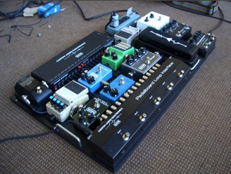
I use Mogami wire and cable almost exclusively. I like the way it sounds, I like the way it preps, I like it. For years. I used Mogami 2319 for this board.Its low capacitance and small diameter makes it great for pedalboards like this. Switchcraft #228 flat right angles and Hosa(PRG-370) connectors were used. I do not use solderless connectors. I just find them to be too unreliable, and not suitable in a professional guitar rig. Plus, they dictate what cable you have to use. I suppose they are fine if you have to put something together quickly, and are not concerned with reliability.
But why make every connection in your rig rely on conductors rubbing up against each other? Its bad enough we have to use ancient 1/4″ phone plug and jack technology to connect everything. But thats the way it is. So my advice to you: If you are going to D.I.Y., learn to solder. Its easier than learning to play guitar, believe me. Or leave it to professionals.
Since there is a relatively large jack count on the PLI,and the jacks are so close together, you have to use the Switchcraft #226 style (Heavy Duty) right angle 1/4″ phone plugs if you want to save board space. I used the Hosa PRG-370’s here. Of course you could use solderless right-angle connectors too(at your own peril).The other alternative is to use straight plugs, but that takes up too much board space for my purpose here.
|
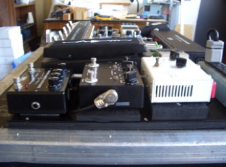
| I elevated the PLI with a wood block (painted black) to allow the use of the” heavy duty” style right angle connectors. I attached the PLI to the wood block with Keystone angle brackets and wood screws.I could have used Dual Lock, or Velcro. I cut other wood block “elevators” (and painted them black) into roughly the shape of the pedals they were supporting,where necessary, and glued them to the metal surface of the pedalboard with GE Household Glue. This wonder stuff I have been using for years. It is clear silicone glue and can be removed fairly easily if necessary, but has a vise grip on almost any surface. |
|
|
|
| Which brings me to attaching the pedals to the board. I use 3M Dual Lock.Part# SJ3560. You could use Velcro, but that requires 2 sexes. I prefer Dual Lock, but it is expensive. Make sure the surfaces are smooth and dry when you attach it, and remove the rubber skid pads and feet from the pedals prior to applying as well.
As I mentioned before, these days I also like to secure wah and volume pedals with brackets and screws, rather than Dual Lock or Velcro, mainly due to the added pressure applied to these pedals due to their foot operation. |
|
IS THIS THING ON?–POWERING UP
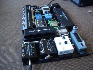
I used the CAE/MXR MC403 Power System to supply power to the pedals and the PLI. I also included a AC plug strip in the upper right hand corner of the board.It was not absolutely necessary, as the MC403 has a detachable AC cord (and accessory outlet) but I figured I may need AC outlets on the board in the future.You never know.
The MC403 Power System worked out great, as some of the pedals required different voltages, and the MC403 handled this with ease.For example, the V-Comp, being a tube device, required 9V AC. No Problem. The PLI and MXR Flanger required 18VDC. Again, no problem. All the other pedals required 9vdc, and all were powered each with an individual isolated 9VDC output. I did have to use the 2 adjustable outputs (set to 9vdc) since I had 10 pedals that required 9vdc, and the MC403 has 8 isolated 9vdc outputs. In all, in addition to the 9vdc outputs(@80ma.each), the MC403 has four isolated 18vdc outputs (@125ma.)each, two isolated outputs adjustable 6.5vdc switchable through 15vdc@200ma. each, and two 9VAC outputs @800ma. each.
If I were to use any other power supply, I would have had to make the board bigger to accommodate the power supplies for all these different voltages. As it is, 1 power supply did the job, with no wall warts in sight, and with power to spare.
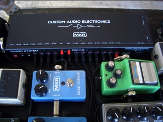 | 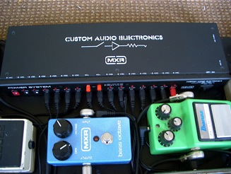 |
I centered the Power System at the top side of the the board, with the Plug Strip just to the left. This allowed a relatively even spread of power distribution to the various pedals. I attached the Power System to the board with the included pedal-board mounting brackets (very handy). As you may recall, I previously drilled holes and installed “t-nuts” to the board at the beginning of this project, just for this purpose. I attached the plug strip in the same way. I made a very short AC cable and plugged the Power System into an outlet on the plug strip.
I then wired the Power System to the pedals with the supplied power cables that came with the unit. For neatness’ sake I opted to cut down the length of the longer cables to make the lengths just right. You can do this easily with these cables as they are of the 2 conductor “zip cord” type, if you feel your soldering skills are up to it. Just use shrink tubing to cover your splices. This is more difficult to do with the jacketed co-axial type of cable. In that case, you would be better off cutting the cable to size, and using a new connector plug. Or better still, order the correct lengths from Dunlop. I tucked the splices under the pedals to keep the wiring looking as pretty as possible. Neatness counts here.
After it was all wired up, I attached a small handle to what little space I had on the left side for ease of portability, and that was it.
All that was left to do was fire it up and see if it works!
TESTING–ONE ,TWO,THREE…
I am happy to say this was the easy part. It all worked like a champ. Clean, quiet, and sounded great. I attribute this to careful planning, clean layout, and good equipment choices. Using a Looping system such as the CAE/MXR Pedalboard Loop Interface certainly helps along with a good isolated output power supply such as the CAE/MXR MC403 Power System.
But you knew I’d say that.
Regardless of what you use, get the highest quality stuff you can afford, especially cables, as they are the links that hold it all together. And I would highly recommend Caig Lab’s DeoxIT D5 contact cleaner for all your pedalboard connections. This stuff is a lifesaver.
